Welcome back!!! We are at Part 5 of the blog series on NSX multitenancy. In this article, we will discuss edge cluster considerations for NSX projects based on a few parameters like topologies, resource guarantees, traffic patterns and throughput. We will also discuss failure domains and their support in NSX projects.
If you were not following along, please check out the previous articles of this series below:
Part 1 – Introduction & Multitenancy models :
https://vxplanet.com/2023/10/24/nsx-multitenancy-part-1-introduction-multitenancy-models/
Part 2 – NSX Projects :
https://vxplanet.com/2023/10/24/nsx-multitenancy-part-2-nsx-projects/
Part 3 – Virtual Private Clouds (VPCs)
https://vxplanet.com/2023/11/05/nsx-multitenancy-part-3-virtual-private-clouds-vpcs/
Part 4 : Stateful Active-Active Gateways in Projects
https://vxplanet.com/2023/11/07/nsx-multitenancy-part-4-stateful-active-active-gateways-in-projects/
Let’s get started:
Edge cluster considerations with respect to topology and resource guarantees for NSX projects
Depending on the topology of the provider gateway & tenant gateways combined with the resource guarantee requirements of the tenants, we have the below choices for edge clusters:
- Stateful A/S tenant T1 gateways up streamed to provider stateless A/A T0 gateway sharing the edge cluster from the provider.
- Stateful A/S tenant T1 gateways up streamed to provider stateless A/A T0 gateway where tenant and provider gateways are on separate edge clusters.
- Stateful A/A tenant T1 gateways up streamed to provider stateful A/A T0 gateway sharing the edge cluster from the provider.
- Stateful A/S tenant T1 gateways up streamed to provider stateful A/A T0 gateway where tenant and provider gateways are on separate edge clusters.
Let’s walk through these scenarios one by one:
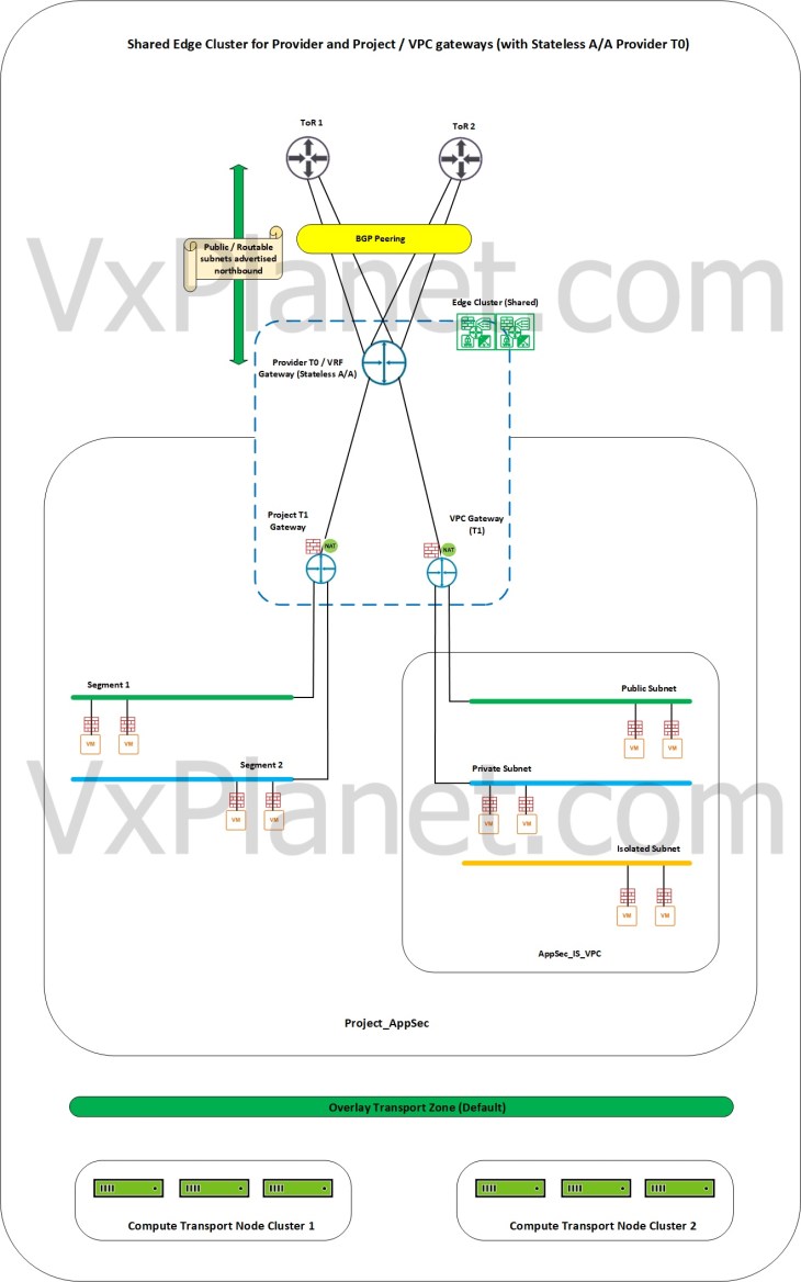
Shared edge cluster for Provider and Tenants with stateless A/A provider gateway
In this scenario, we have a stateless A/A provider T0 gateway and the provider edge cluster (hosting the provider T0 gateway) is shared across one or more tenants and their respective VPCs. Resources from the provider edge cluster will be consumed by all the tenants (limited by the configuration maximums), and as such resource guarantees are not assured to the tenants (however we can restrict the tenant consumption to some extend using project quotas)
Dedicated edge cluster for Provider and Tenants with stateless A/A provider gateway
In this scenario, we have a stateless A/A provider T0 gateway and have dedicated edge clusters for provider and tenants. Each tenant thus gets a dedicated pool of edge resources for consumption and as such, resource guarantees to tenants are assured. Note that all edge clusters need to be prepared on the same default overlay transport zone.
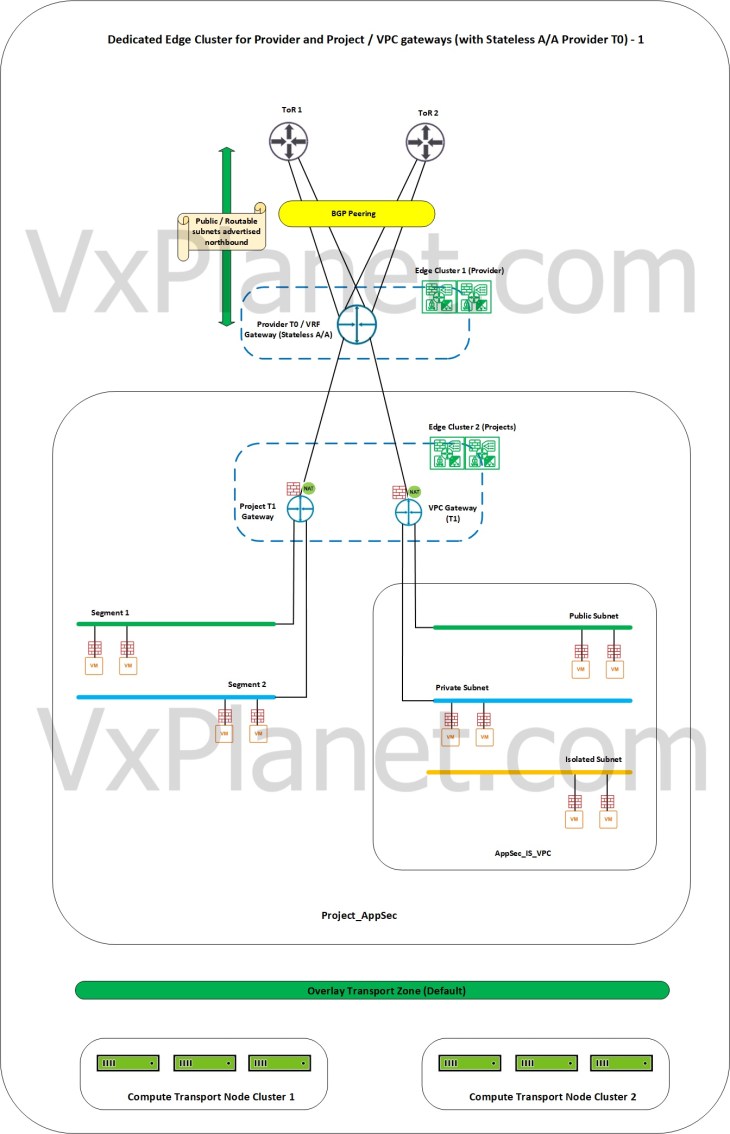
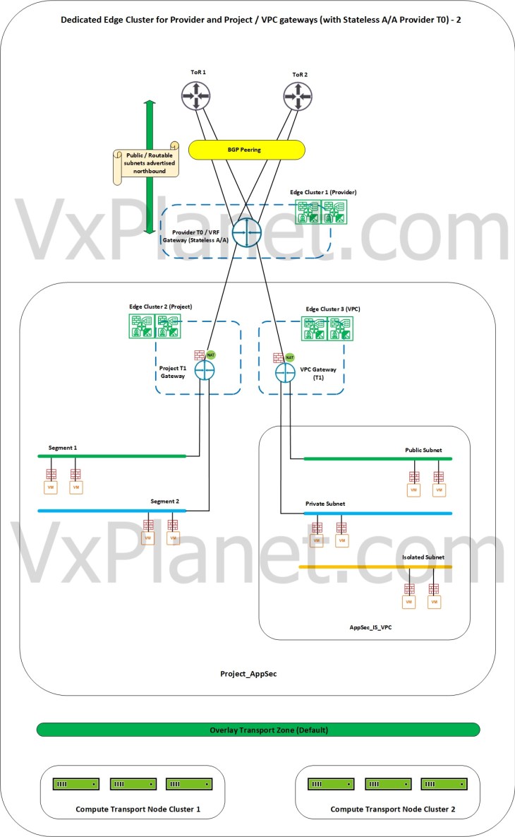
The above scenario can be extended to VPCs in the projects as well, by assigning a dedicated edge cluster to VPCs based on requirements.
Shared and dedicated edge clusters with stateful A/A provider gateway
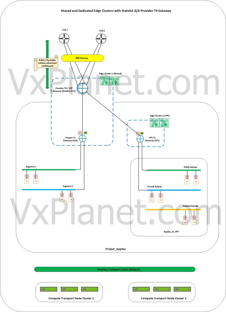
In this scenario, we have a stateful A/A provider T0 gateway and the provider edge cluster (hosting the T0 gateway) is shared across one or more tenants in order to host the tenant’s stateful A/A T1 gateways. We also have dedicated edge clusters assigned to the tenant in order to support tenant’s requirements for stateful A/S T1 gateways too.
VPCs only support A/S T1 gateways, hence they require a dedicated edge cluster if the upstream provider gateway is stateful A/A.
Edge cluster considerations with respect to northbound ECMP and throughput
The choice of shared edge cluster vs dedicated edge cluster for the tenants influences the northbound traffic patterns and ECMP. Let’s discuss these scenarios one by one.
Northbound flow from project A/S T1 gateways attached to stateless A/A provider T0 gateway with a shared edge cluster
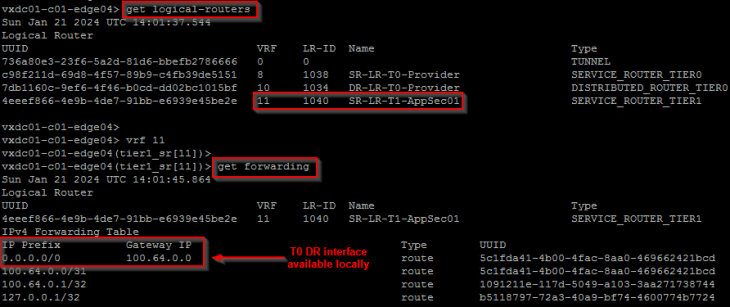
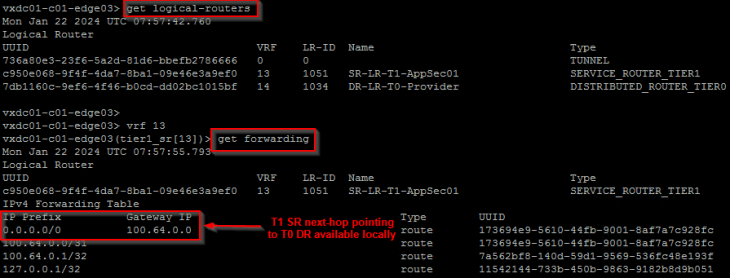
In this scenario, we see that the active edge node hosting the T1 SR construct of the project gateways is involved in all the northbound lookups up to the physical fabric. Traffic forwarding happens locally on the edge node as soon as the T1 SR lookup is completed, and as such, we see reduced northbound ECMP paths from the project gateways to the external networks as depicted below.
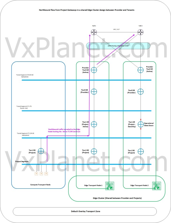
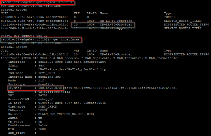
Below shows the forwarding table of a project T1 SR construct that is next-hopping to the T0 DR construct which is available locally on the edge node. T0 SR lookup also happens locally on the same edge node and traffic will egress out to the external fabric over the local edge uplinks.
For more detailed explanation of the above scenario, please refer to my earlier article on T1 SR placement below:
Northbound flow from project A/S T1 gateways attached to stateless A/A provider T0 gateway with a dedicated edge cluster
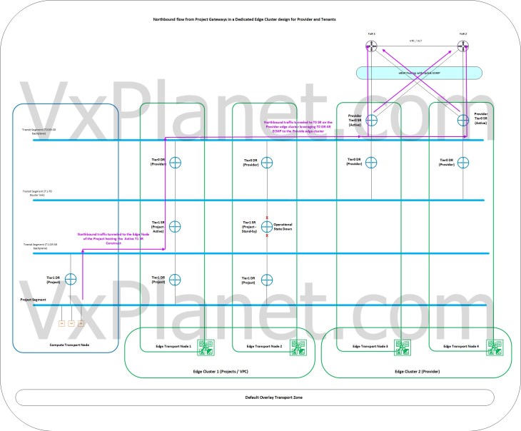
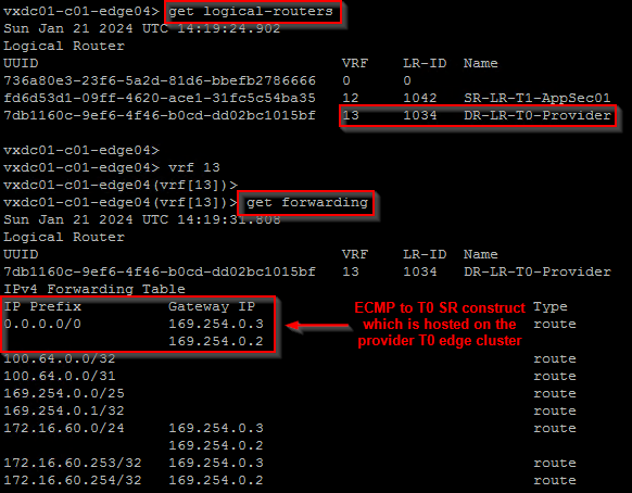
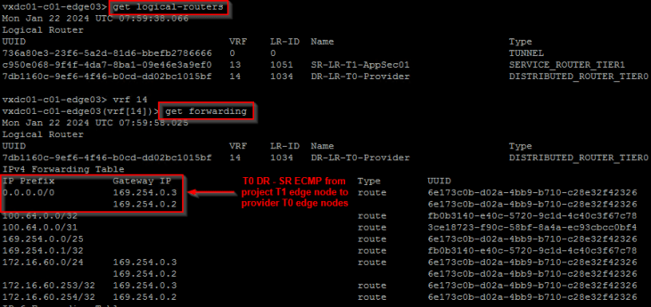
In this scenario, we see that the active edge node hosting the T1 SR construct of the project gateways does an ECMP forwarding to both edge nodes in the provider T0 edge cluster after the T0 DR – SR lookup. This ECMP is scalable to additional edge nodes in the provider edge cluster as provider edge cluster is scaled out with additional edge nodes. As such, we see increased northbound ECMP paths from the project gateways to the external networks as depicted below.
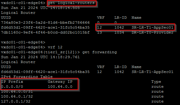
Below shows the forwarding table of a project T1 SR that is next-hopping to the T0 DR construct which is available locally on the edge node, but does ECMP next-hop for the T0 SR construct which is on the provider edge cluster.
For more detailed explanation of the above scenario, please refer to my earlier article on T1 SR placement below:
Northbound flow from project A/A T1 gateways attached to stateful A/A provider T0 gateway with a shared edge cluster
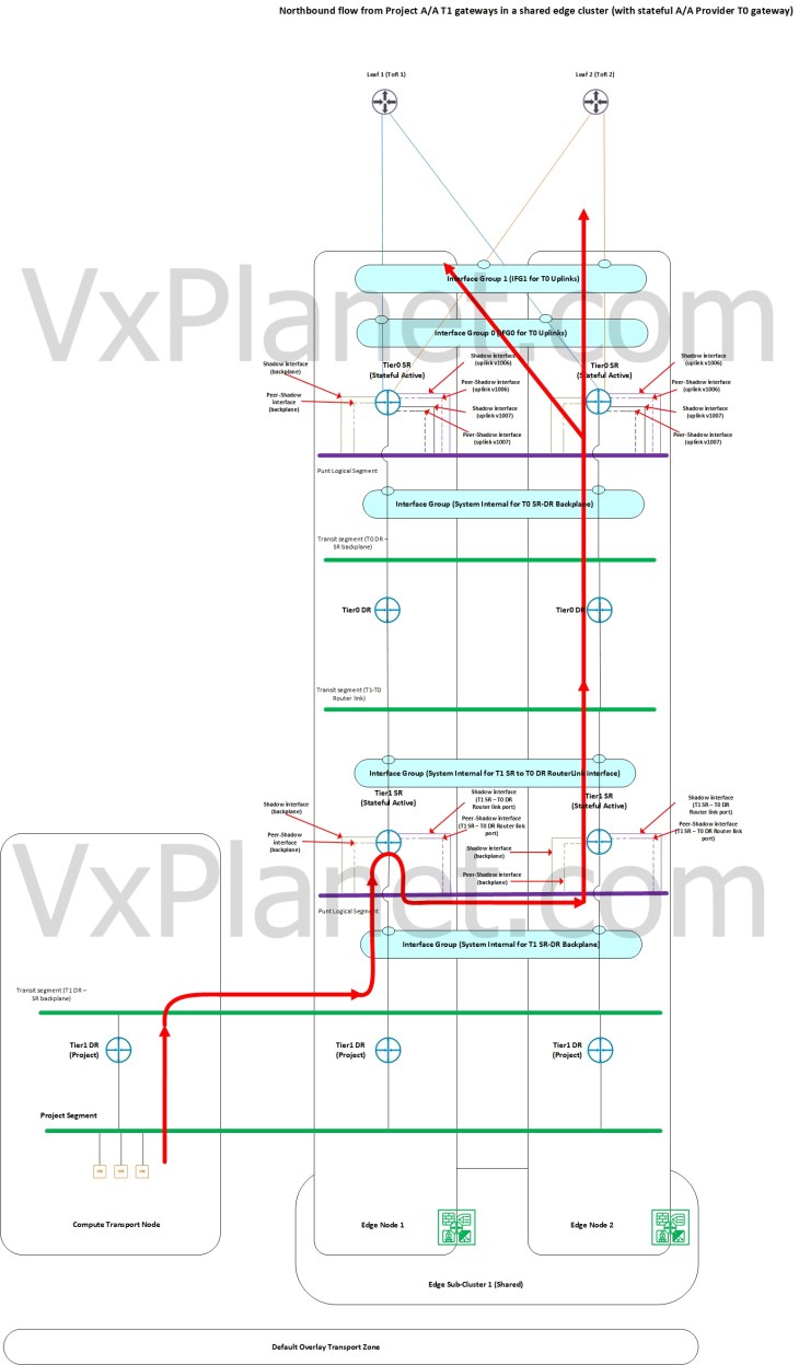
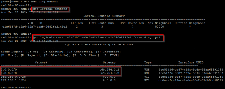
To host a stateful A/A T1 gateway in a project up streamed to stateful A/A provider T0 gateway, it’s a requirement to share the edge cluster of the provider stateful A/A T0 gateway with the project T1. In this scenario, we see that there is T1 DR – SR ECMP from the host transport nodes to the shared edge cluster. Once traffic is forwarded to one of the edge nodes in the edge cluster based on T1 DR-SR ECMP hash, traffic will be punted to one edge node in an edge sub-cluster who is authoritative to store the stateful information for the flow. This punting is based on a hash of the destination IP address of the flow. All further northbound lookup happens locally on this edge node.
In this scenario, we have increased northbound ECMP paths as each flow will be hashed to a separate edge node that does the local forwarding northbound.
Below shows the forwarding table of a project T1 DR construct (which is on a host transport node) that does ECMP next hop to the T1 SR constructs on all the edge nodes in the edge cluster.
For more detailed explanation of the above scenario, please refer to my earlier article on stateful A/A gateway packet-walks below:
Note: Not all stateful services are currently supported in stateful A/A configuration. Please check the official documentation to see which all services are currently supported.
Northbound flow from project A/S T1 gateways attached to stateful A/A provider T0 gateway with a dedicated edge cluster
To host a stateful A/S T1 gateway in a project up streamed to stateful A/A provider T0 gateway, it’s a requirement to have a dedicated edge cluster for the project to host the project T1. In this scenario, we see that traffic will be routed northbound by the active edge node hosting the project T1 SR construct and after the T0 DR lookup locally, traffic will be ECMP’ed to the provider edge nodes hosting the T0 SR construct. Traffic will then be the punted to one edge node within the provider edge sub-cluster who is authoritative to store the stateful information for the flow. This punting is based on a hash of the destination IP address of the flow. All further northbound lookup happens locally on this provider edge node. We see that there is T0 DR – SR ECMP happening between the project edge cluster and the provider edge cluster.
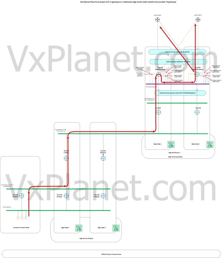
Below shows the forwarding table of a project T1 SR that is next-hopping to the T0 DR construct which is available locally on the edge node, but does ECMP next-hop for the T0 SR construct which is on the provider edge cluster.
For more detailed explanation of the above scenario, please refer to my earlier article on stateful A/A gateway packet-walks below:
Failure Domains
NSX multitenancy (projects) honors the failure domains configured on the edge clusters that are shared with the projects. For eg: for a project T1 gateway configured in A/S mode, the SR constructs are always placed on edge nodes belonging to separate failure domains (or availability zones). Similarly for a project T1 gateway in A/A mode, the edge sub-clusters will always choose member edge nodes that are from separate failure domains.
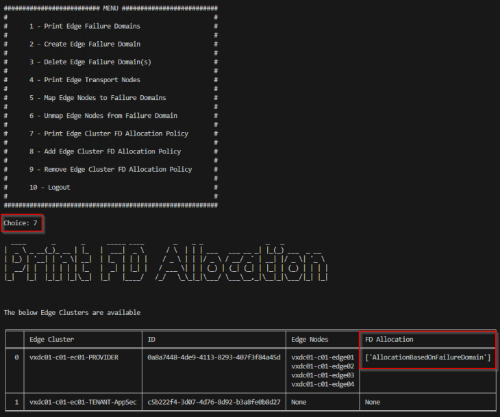
Just FYI, I created a python project last year to automate the creation of failure domains and manage the mapping of edge nodes to failure domains. The project is hosted at https://github.com/harikrishnant/NsxFailureDomainCreator
If you recollect, we used this tool previously while doing the blog series on stateful active-active gateways. You can check out part 4, that covered edge sub-clusters and failure domains.
We will use this tool again for this article. Once the tool completes it’s job, we will have the edge nodes in the provider edge cluster mapped across two failure domains – AZ01 and AZ02.

We will now validate two scenarios:
In scenario 1, we will spin up an A/S T1 gateway inside the AppSec project attached to a stateless A/A provider T0 gateway and confirm that the SR constructs are placed across the two failure domains.
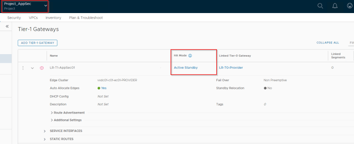
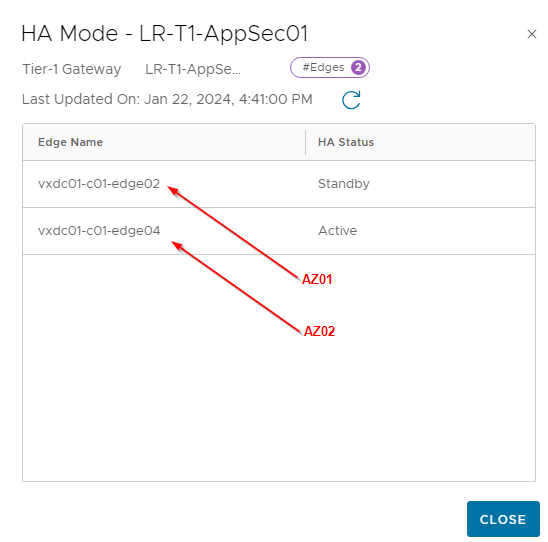
As seen, the project T1 SRs are placed on vxdc01-c01-edge02 and vxdc01-c01-edge04 which are on failure domains AZ01 and AZ02 respectively.
In scenario 2, we will spin up a stateful A/A T1 gateway inside the AppSec project attached to a stateful A/A provider T0 gateway and confirm that the edge subclusters hosting the project T1 SRs are created with edge nodes from separate failure domains (AZ01 and AZ02)
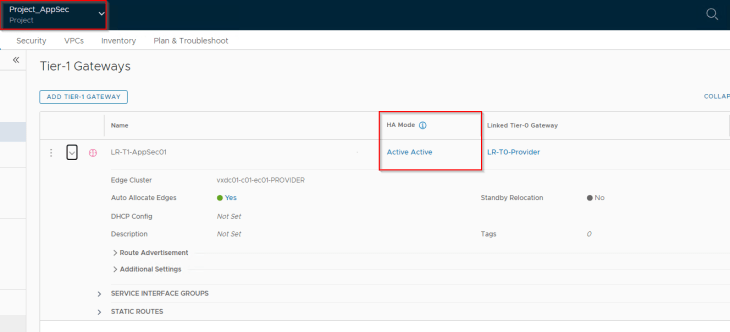
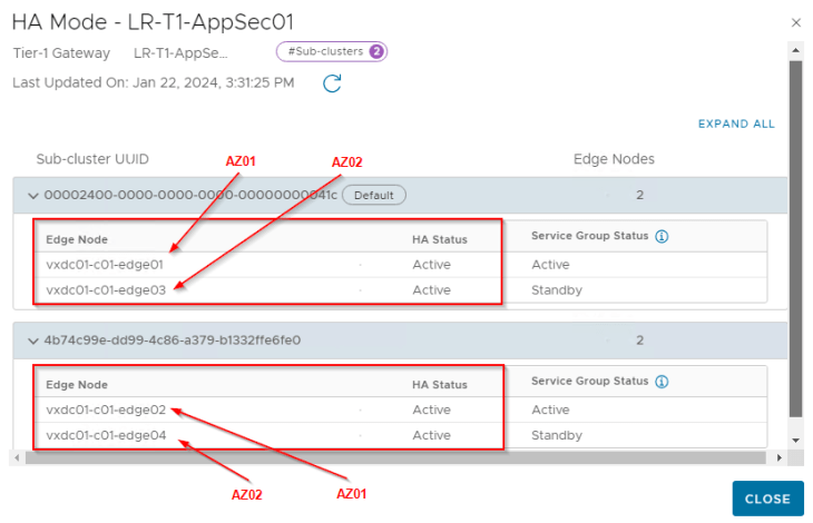
As seen, the edge subcluster 1 has vxdc01-c01-edge01 and vxdc01-c01-edge03 which are on failure domains AZ01 and AZ02 respectively. Similarly, edge subcluster 2 has vxdc01-c01-edge02 and vxdc01-c01-edge04 which are on AZ01 and AZ02 respectively.
Let’s wrap up and break for coffee. In the next part, we will discuss the integration of advanced load balancing for NSX projects and VPCs. Stay tuned!!!
I hope this article was informative. If VxPlanet.com helped you in your NSX journey and you’d like to offer me a coffee, here is the link:

Continue reading? Here are the other parts of this series:
Part 1 – Introduction & Multitenancy models :
https://vxplanet.com/2023/10/24/nsx-multitenancy-part-1-introduction-multitenancy-models/
Part 2 – NSX Projects :
https://vxplanet.com/2023/10/24/nsx-multitenancy-part-2-nsx-projects/
Part 3 – Virtual Private Clouds (VPCs):
https://vxplanet.com/2023/11/05/nsx-multitenancy-part-3-virtual-private-clouds-vpcs/
Part 4 : Stateful Active-Active Gateways in Projects:
https://vxplanet.com/2023/11/07/nsx-multitenancy-part-4-stateful-active-active-gateways-in-projects/
Part 6 : Integration with NSX Advanced Load balancer
https://vxplanet.com/2024/01/29/nsx-multitenancy-part-6-integration-with-nsx-advanced-load-balancer/


