Welcome to the final part of the blog series on NSX multitenancy. In this article, we will discuss the integration with NSX Advanced Load balancer to offer advanced load balancing as a service (ALBaaS) to the NSX tenants. Lets’ get started:
If you were not following along, please check out the previous articles of this blog series below:
Part 1 : Introduction & Multitenancy models :
https://vxplanet.com/2023/10/24/nsx-multitenancy-part-1-introduction-multitenancy-models/
Part 2 : NSX Projects :
https://vxplanet.com/2023/10/24/nsx-multitenancy-part-2-nsx-projects/
Part 3 : Virtual Private Clouds (VPCs) :
https://vxplanet.com/2023/11/05/nsx-multitenancy-part-3-virtual-private-clouds-vpcs/
Part 4 : Stateful Active-Active Gateways in Projects :
https://vxplanet.com/2023/11/07/nsx-multitenancy-part-4-stateful-active-active-gateways-in-projects/
Part 5 : Edge Cluster Considerations and Failure Domains :
https://vxplanet.com/2024/01/23/nsx-multitenancy-part-5-edge-cluster-considerations-and-failure-domains/
NSX ALB dataplane design for NSX tenants
The data plane of NSX Advanced load balancer is hosted on dedicated appliances called service engines. There are two NSX ALB service engine design choices available depending on the resource guarantees and the level of isolation required for NSX tenants.
- Shared Service Engine Group (SEG) design
- Dedicated Service Engine Group (SEG) design
Shared SEG design
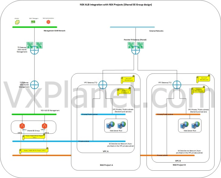
In a shared SEG design, all NSX tenants (including the tenant VPCs) share the Service Engines (SE) from a common Service Engine Group to host their virtual services. That means, the ALB data plane is shared across all NSX tenants and tenant isolation is achieved using dedicated NSX ALB VRF contexts. Each VPC in an NSX project that gets enabled for advanced load balancing will plumb a data interface on the service engines, which map to a dedicated VRF context in the service engines. An SE supports a max of 10 data interfaces, and hence up to 10 VPC gateways can be attached to an SE (unless limited by the hypervisor). As the SE data interfaces attach to respective VPC Gateways (T1) over a dedicated VRF context, the virtual services of each NSX tenant / VPC will be confined to the respective VRFs in SE, and hence isolated from other NSX tenants / VPCs.
In a shared SEG design, SEs are typically sized to accommodate all the NSX tenant requirements and there are no tenant specific resource guarantees or quotas to be applied to SEGs as such. The below sketch shows a shared SEG design for NSX tenants:
Dedicated SEG design
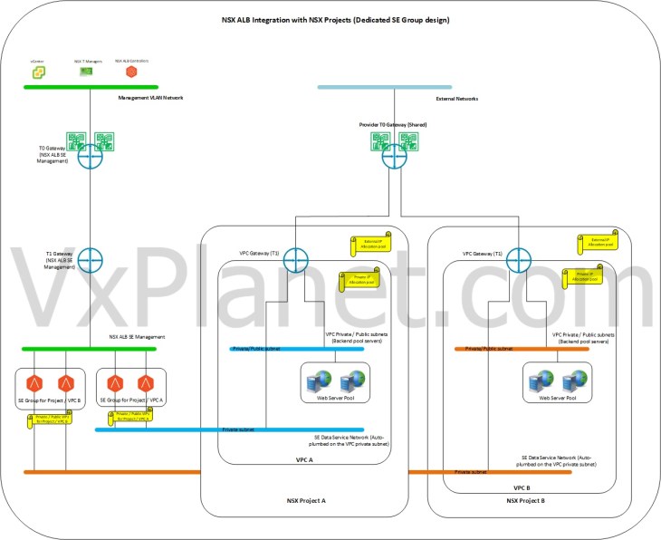
In a dedicated SEG design, each NSX tenant / VPC gets a dedicated service engine group to host their virtual services. In this design, the service engine resources are completely available for the respective NSX tenant for consumption. In other words, there is a 1:1 mapping (soft mapping) between the NSX tenants / VPCs with the service engine group. This design is suitable for NSX tenants who require guaranteed SE resources and higher level of isolation to host their virtual services.
The below sketch shows a dedicated SEG design for NSX tenants:
Current NSX environment
Before we proceed to the integration topic, let’s walk through the current multitenant NSX environment which we implemented in parts 2 & 3.
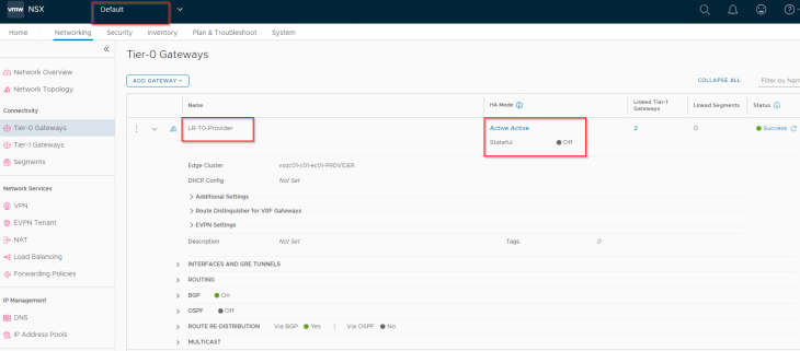
We have a single provider stateless A/A T0 gateway that is shared across NSX projects and VPCs.
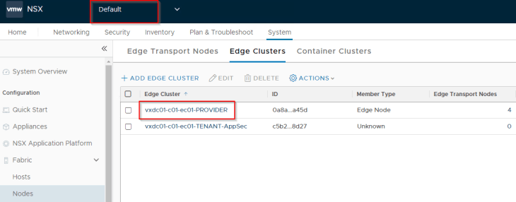
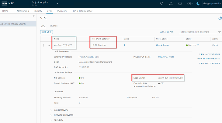
The provider edge cluster “vxdc01-c01-ec01-PROVIDER” is also shared with NSX projects and VPCs to host the project T1 gateways.
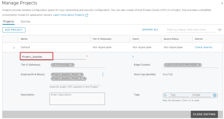
We have a single NSX project called “Project_AppSec” and the LDAP group “AppSec_Project_Admins@vxplanet.int” is granted Project Admin privileges to the project.

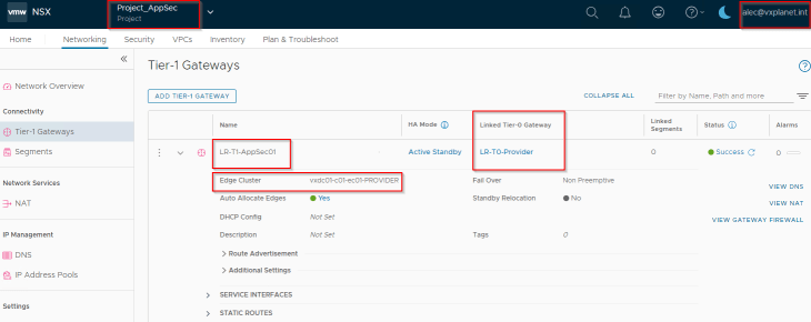
“Project_AppSec” has an A/S T1 gateway sharing the provider edge cluster to host the project workloads.
“Project_AppSec” has a VPC called “AppSec_OTS_VPC” for the OTS Application team and the LDAP group AppSec_OTS_VPC_Admins@vxplanet.int is granted VPC Admin privileges to the VPC.
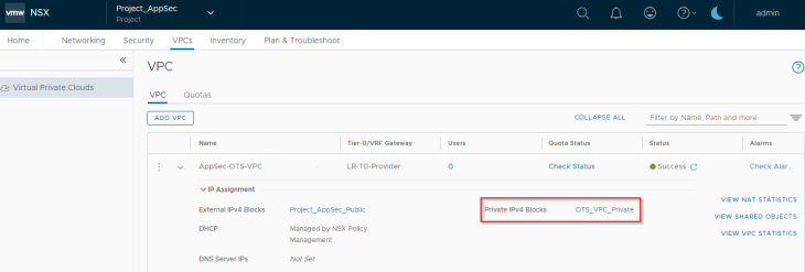
Note that we have also associated an external and private IP block for use with Public and Private subnets in the VPC.

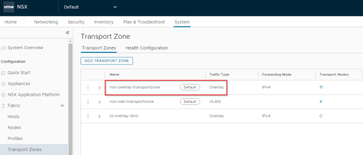
And remember, NSX projects support only the default overlay transport zone currently and as such, all the transport nodes are prepared with the “nsx-overlay-transportzone” (highlighted below).
Current NSX ALB environment
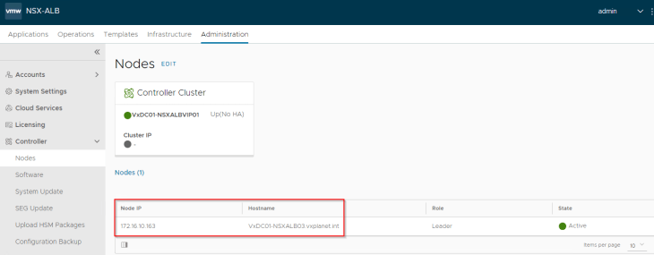
We have a single node NSX ALB Controller cluster (version 30.1.2) deployed for the integration purpose. Currently, only one NSX ALB cluster with NSX Cloud enabled with VPC mode is allowed to provide load balancing for a single NSX Manager. That is, only 1:1 mapping of NSX ALB and NSX Manager is allowed, if VPC support needs to be enabled. For additional limitations with the integration, please check out the official documentation at:
https://docs.vmware.com/en/VMware-NSX-Advanced-Load-Balancer/30.1/Installation-Guide/GUID-70393EC3-2995-4439-B813-1E20C3D475DF.html
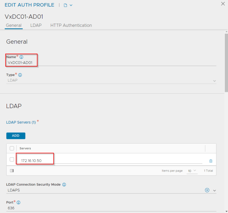
We have created an authentication profile (LDAP) in order to allow RBAC for Active Directory groups to access NSX ALB. This is required in order to map NSX roles (Enterprise Admins, Project Admins and VPC Admins) to NSX ALB roles (System Admin, Tenant Admin and Application Admin respectively)

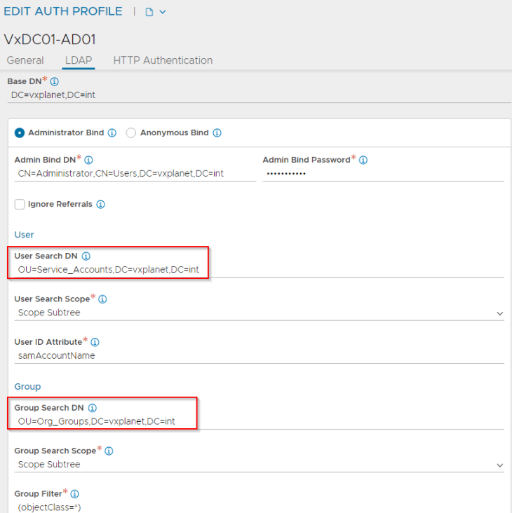
In the authentication profile, we have defined an LDAPS (TCP 636) connection to Active Directory 172.16.10.50.
The fields for “User Search DN” and “Group Search DN” will define the scope for AD user and group search in Active Directory. We will target these field closer to the OU where they belong (in order to narrow down the search)
Let’s perform a basic test. We will lookup alec@vxplanet.com (who is the project admin) and confirm that the LDAP query succeeds.
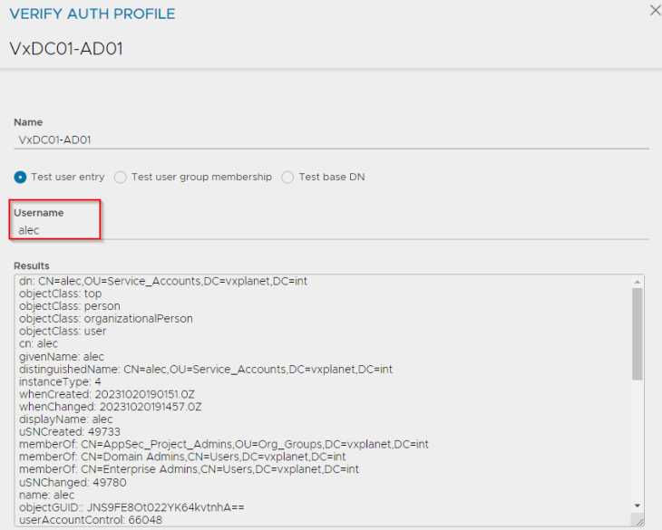
At this moment, the LDAP authentication profile looks good, however we will not enforce this authentication profile now and will do in the subsequent sections.
Defining the NSX ALB Management Networks
The NSX ALB controller cluster is deployed on the management VLAN (on vCenter port-groups) adjacent to other management components (NSX managers, vCenter server etc)
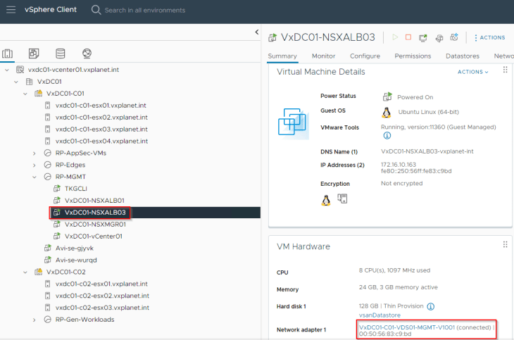
Service engines are deployed on NSX overlay segments and as such, we define a dedicated management path for the SE to NSX ALB Controller communication. This means, we have a dedicated NSX segment, T1 gateway and optionally a T0 gateway to facilitate SE to controller communication. Note that all these are created on the default space by the NSX Enterprise administrator (on the default overlay transport zone).
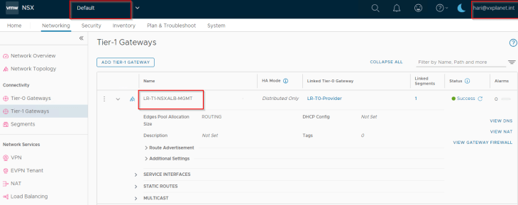
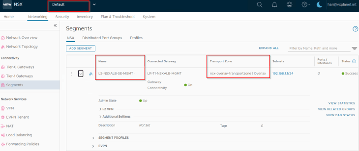
We have also configured a segment DHCP profile to automate IP addressing for the SE management interface.
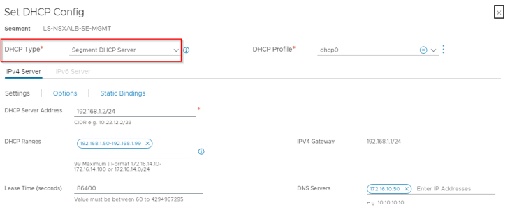
Note : If DFW is enforced, make sure the necessary management ports are allowed between SEs and the controller cluster.
Advanced load balancing for the default space
Now let’s discuss setting up advanced load balancing for the default space.
Defining RBAC for NSX Enterprise Admins
Remember, we defined an authentication profile earlier, but didn’t enforce it. Now let’s define an RBAC policy in order to map NSX Enterprise Admins to System Admins in NSX ALB. We do that using “Auth mapping profile” in NSX ALB.

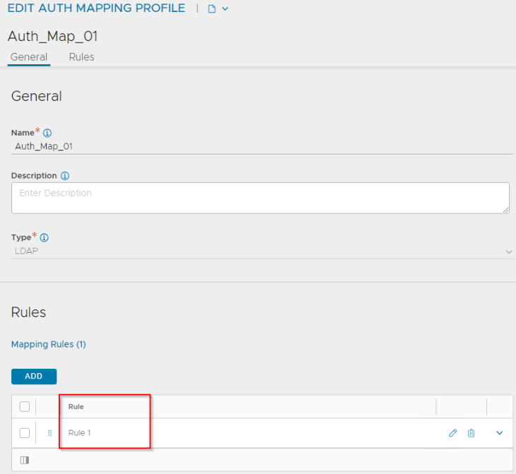
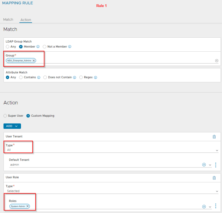
Rule 1 has the definition to map the LDAP group “NSX_Enterprise_Admins” as System Admin to all tenants in NSX ALB. This is because System admins perform the infrastructure and related configurations in NSX ALB.
Let’s enforce the authentication profile. Basically, we link the authentication mapping profile to the authentication profile and then switch the authentication mode to remote.
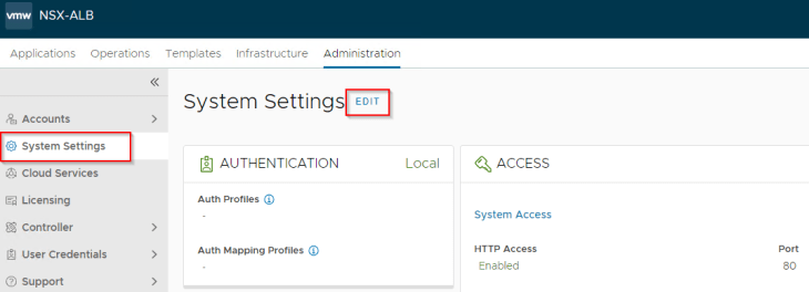
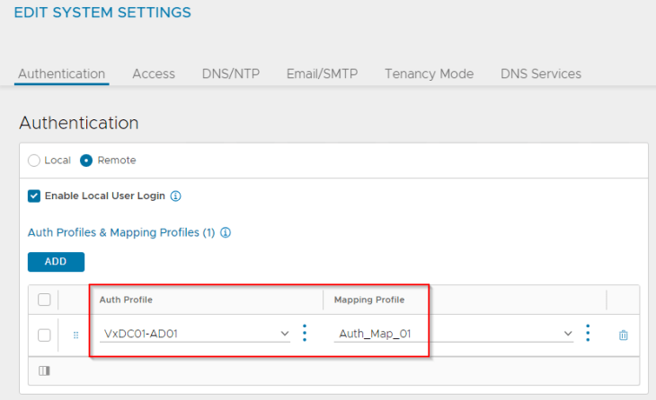
Let’s login as hari@vxplanet.com who is the NSX Enterprise Admin (and now NSX ALB System Admin) and confirm the access.

Optionally, NSX ALB system admin can now define access to other LDAP groups based on role requirements (like application admin etc)
Defining the NSX ALB data networks
Next, we define a dedicated data segment created in the default space where the SE data interface attaches to. We also configure segment DHCP in order to automate the IP addressing for the SE data interface.
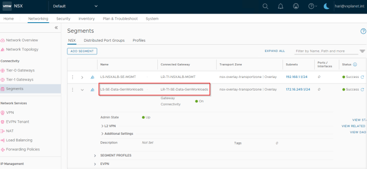
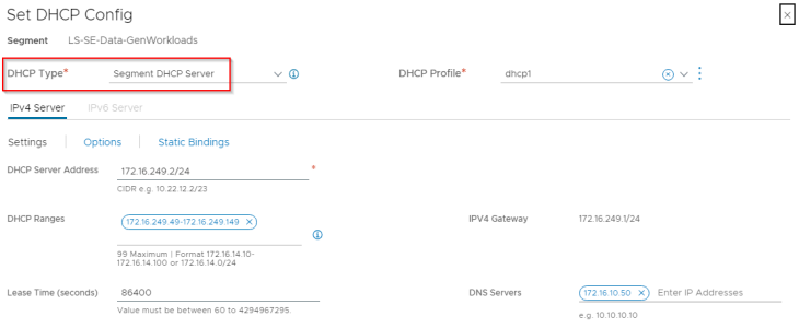
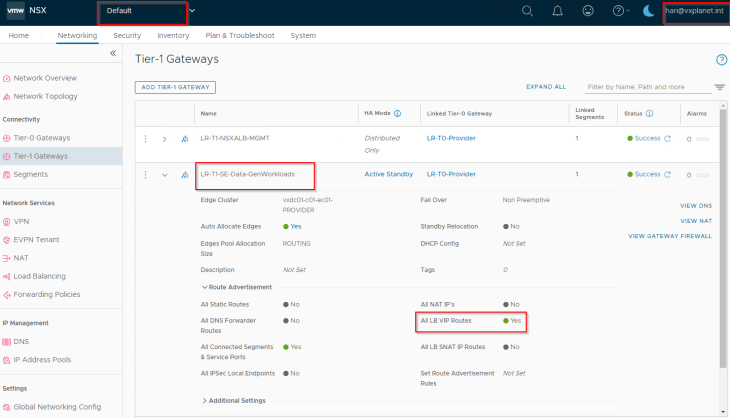
This data segment attaches to a dedicated data T1 gateway which will be mapped as data network in the NSX cloud connector. T1 route advertisements for connected segments and LB VIPs will be enabled for VIP reachability.
Configuring the NSX cloud connector
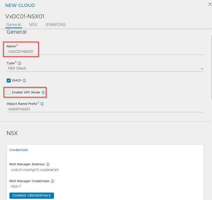
Cloud connector configuration is done by the NSX ALB system admin (hari@vxplanet.int, in this case) and is scoped under the admin tenant. Tenant scoped cloud connector is currently not supported in VPC mode.

The checkbox for DHCP needs to be enabled, in order to point the SE interfaces to DHCP. Since our objective in this section is to configure load balancing only for the default space, we can leave the checkbox for “Enable VPC mode” to blank. We will enable this flag later.
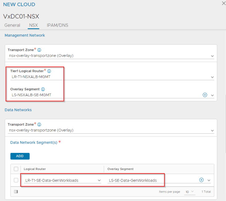
Next, we will define the mapping of T1 gateways and segments for the management plane and data plane.
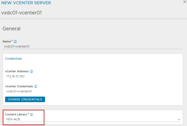
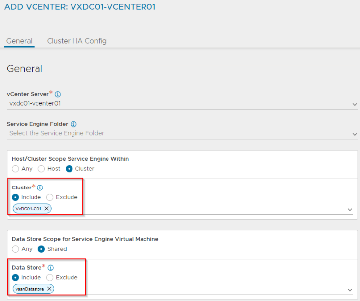
The NSX compute manager (vCenter server) where the SEs will be deployed needs to be defined along with a content library where the SE images can be pushed to.
Once the cloud connector is configured, we see that the data T1 gateway is mapped as a dedicated VRF context (routing domain) in NSX ALB.

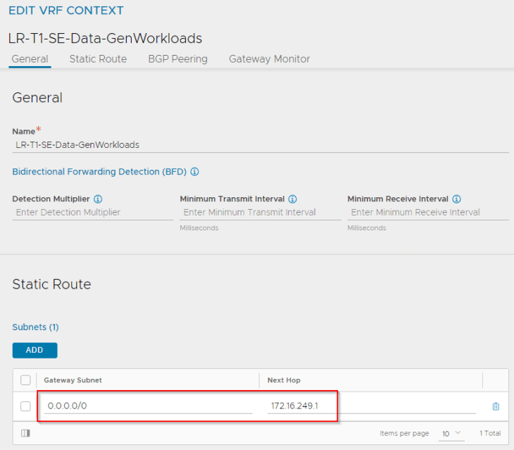
Let’s define a default route for the VRF context that points to the data segment’s gateway on the T1.
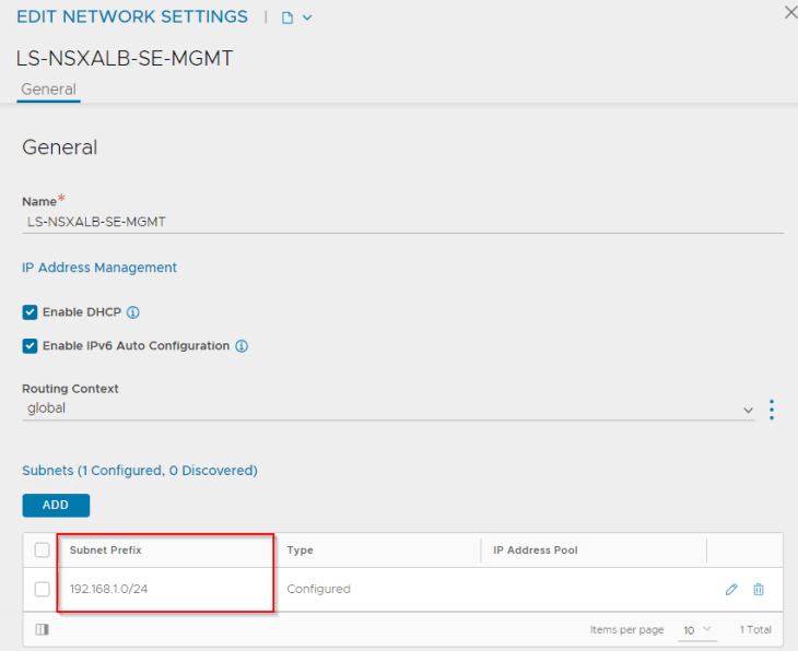
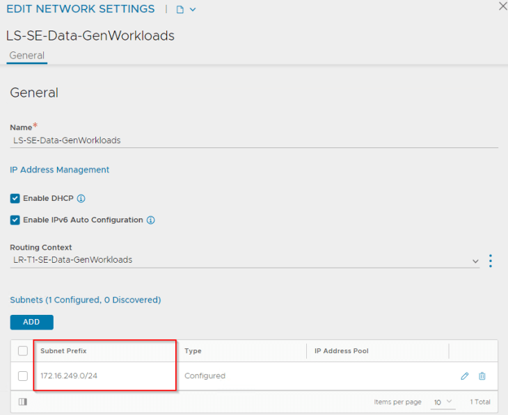
We see that the segments appear under Network Profiles, and we will update the subnet information for the networks.

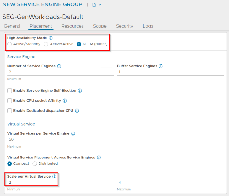
We will create a service engine group (SEG) under the NSX connector that defines the configuration of service engines like the HA mode, sizing, placement scope, scale, reservations, ageing etc.

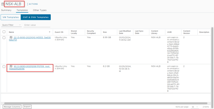
We also see that an SE ova template (v30.1.2) is pushed automatically by the NSX ALB controller to the vCenter content library. This will be queried when a new SE needs to be deployed.
At this moment, we see that the NSX cloud connector configuration is complete, and the load balancing services are now available to the default space.

Creating virtual services
Virtual services are created from the NSX ALB interface by the application admin (or those with the necessary privileges)

Virtual services are created under the NSX cloud connector on the data VRF context that we defined previously.

Let’s create a test virtual service and place it under the SE group that we defined previously.
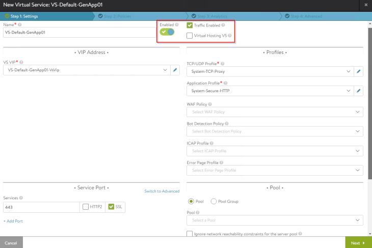
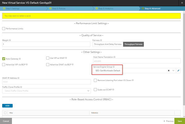
NSX Cloud connector will orchestrate the deployment of new service engines to host this virtual service (as no service engines already existed under the service engine group).

We also see that the SE data interface is mapped to the respective VRF Context (T1 gateway under which the virtual service was created)
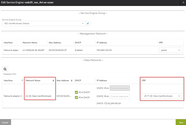
The virtual service should come up and will be available for access.

Advanced load balancing for VPCs
Now let’s discuss setting up advanced load balancing for the VPCs in NSX projects.
Configuring the NSX cloud connector
We need to edit the NSX cloud connector that we created previously to enable the flag for VPC support. By enabling VPC mode in the cloud connector, NSX ALB will start discovering all the VPCs in NSX projects that have the ALB flag set, and dynamically update the data networks in the cloud connector accordingly.
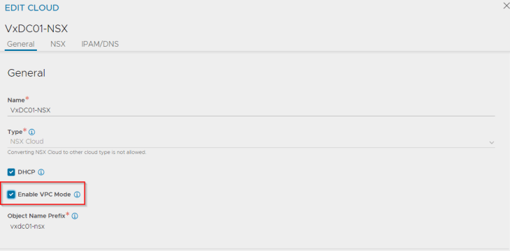
Note : The flag setting for VPC mode is immutable.
Configuring the VPC
We will now configure the “AppSec_OTS_VPC” in Project_AppSec, so that it will be discovered by the NSX cloud connector in NSX ALB.
We have a private subnet created in the VPC where the application servers (LB pool members) are connected.
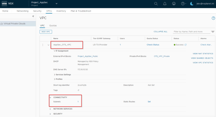

Let’s turn the ALB flag to ON to enable discovery by NSX ALB.
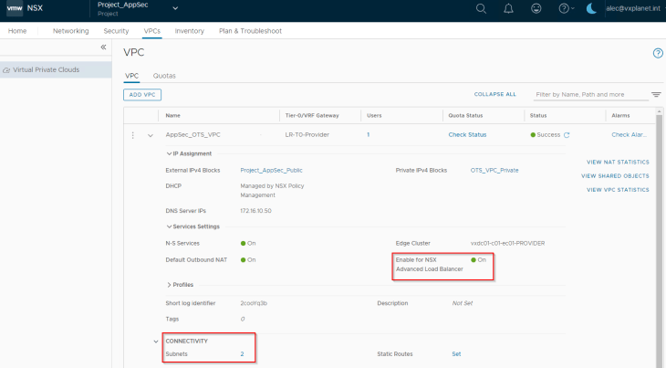
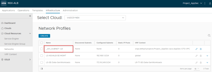
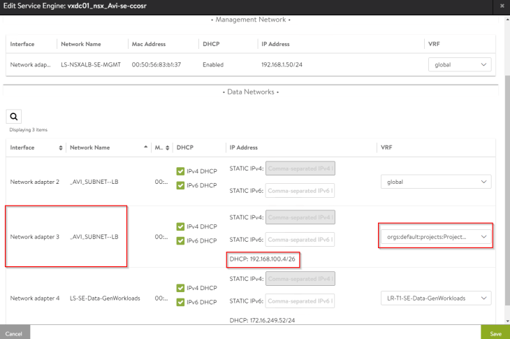
We see that a new private subnet “_AVI_SUBNET-LB” is auto-plumbed into the VPC. This will be used as the data segment for the service engines.

Both private subnets will be attached to the VPC T1 gateway “AppSec_OTS_VPC”. This will be mapped as a VRF context in NSX ALB. In short, for each discovered VPC, a dedicated tenant-scoped VRF context will be created in NSX ALB.

Mapping NSX Projects to NSX ALB Tenants
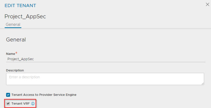
For each NSX project that is discovered by the NSX cloud connector, an equivalent tenant is created in NSX ALB. The discovered VPCs that are mapped as VRF contexts, are scoped under the tenant, and hence the flag for “Tenant VRF” is enabled by default.

Defining RBAC for NSX Project Admins and NSX VPC Admins
Earlier, we defined an RBAC policy for NSX Enterprise Admins who were mapped as NSX ALB System Admins.
We will modify the mapping profile to define the below additional associations:
- NSX Project Admins will be mapped as NSX ALB Tenant Admins
- NSX VPC Admins will be mapped as NSX ALB Application Admins
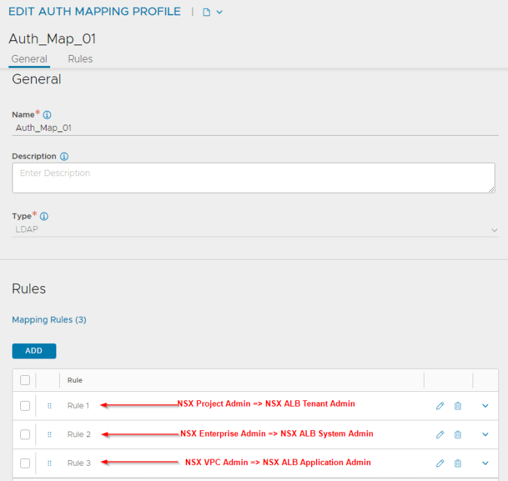
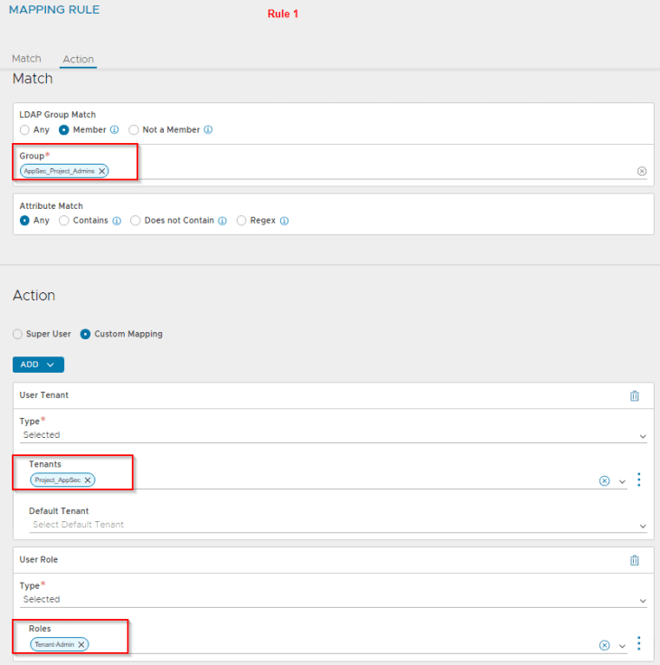
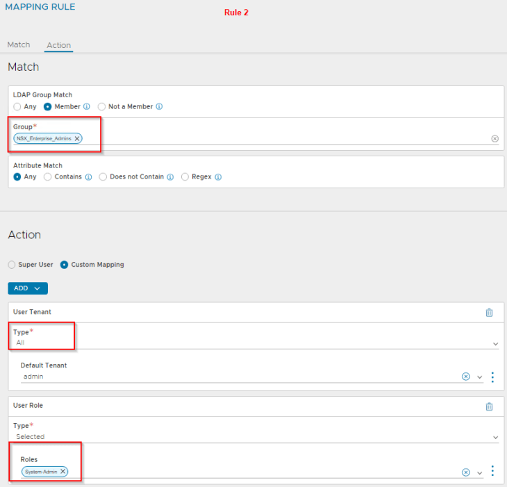
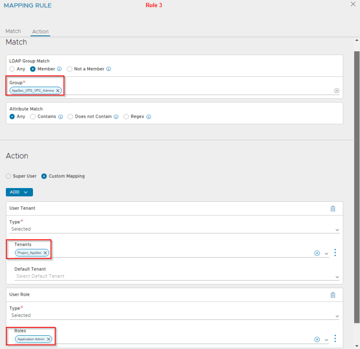
Let’s login as ben@vxplanet.int who is the NSX VPC Admin (and now NSX ALB Application Admin) and confirm the access.

VRF Contexts and Networks
At this moment, we see that the data networks are dynamically updated in the NSX cloud connector with the VPC gateway and data segment information.
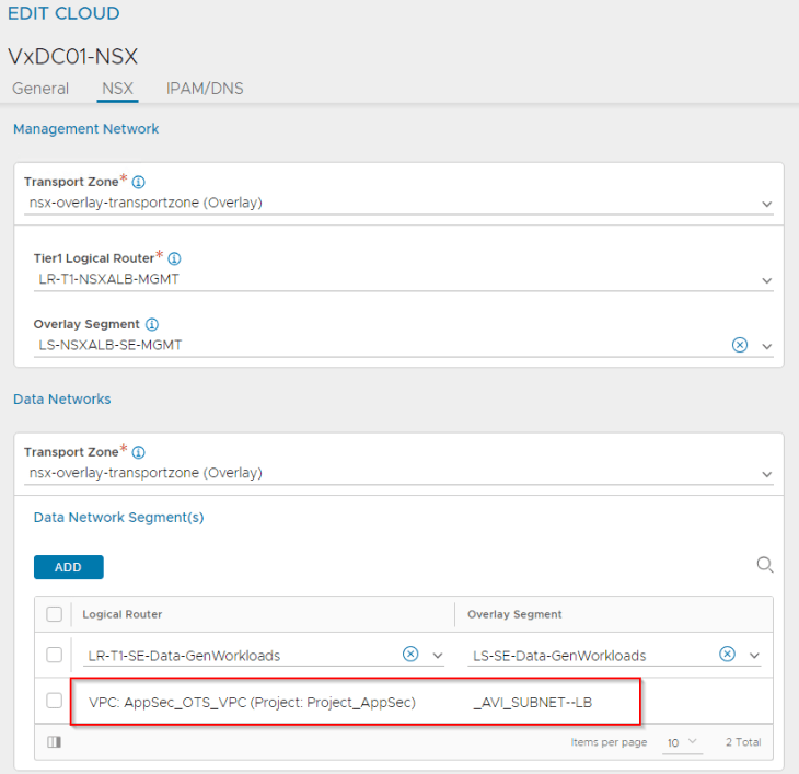
A dedicated VRF context will be created for each discovered VPC (because each VPC is in it’s own T1 gateway in NSX)

Creating virtual services
Virtual services are created from the NSX ALB interface by the application admin (or those with the necessary privileges) under the respective NSX ALB tenant.

Note : Make sure the context is switched to the “Project_AppSec” tenant as the VRF context (VPC) is tenant scoped.
Virtual services are created under the NSX cloud connector on the respective data VRF context (VPC).


Let’s create a test virtual service and place it under the SE group that we defined for the default space previously (shared SEG model). We could also define a new SE group dedicated to the project / VPC also (dedicated SEG model).
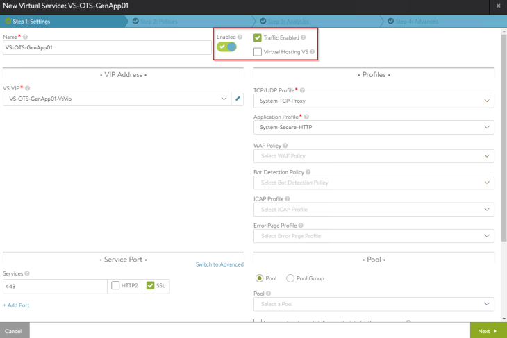
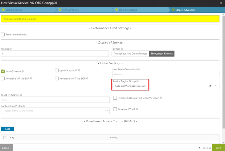
We have two options to place the VIPs for VPCs:
- On the private subnet (this is not routable externally)
- On the public subnet (this is routable externally)
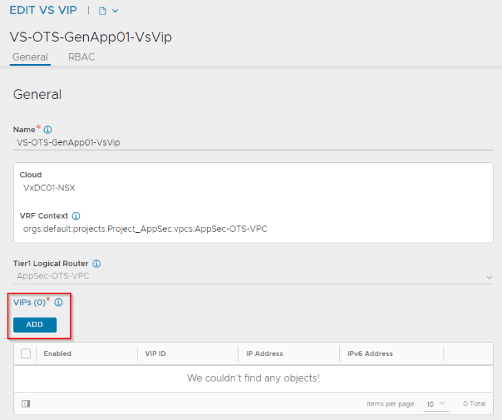
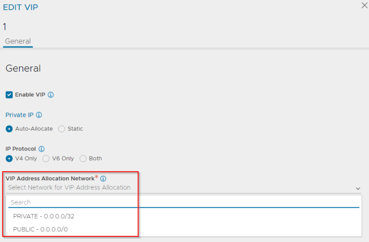
Selecting the “PUBLIC” option will create an L3 VIP with an IP from the External IP allocation pool (which is routable)

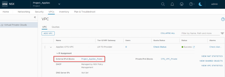
Selecting the “PRIVATE” option will create an L2 VIP with an IP from the Private IP allocation pool (which is not routable)

We see that the SE data interface is mapped to the respective VRF Context of the VPC and gets an interface IP from the private auto-plumbed subnet.
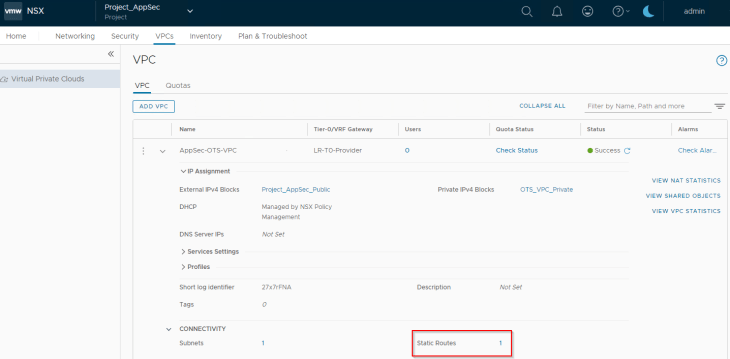
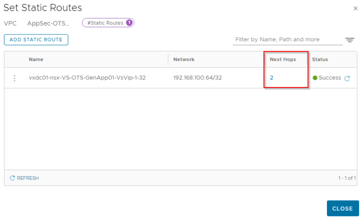
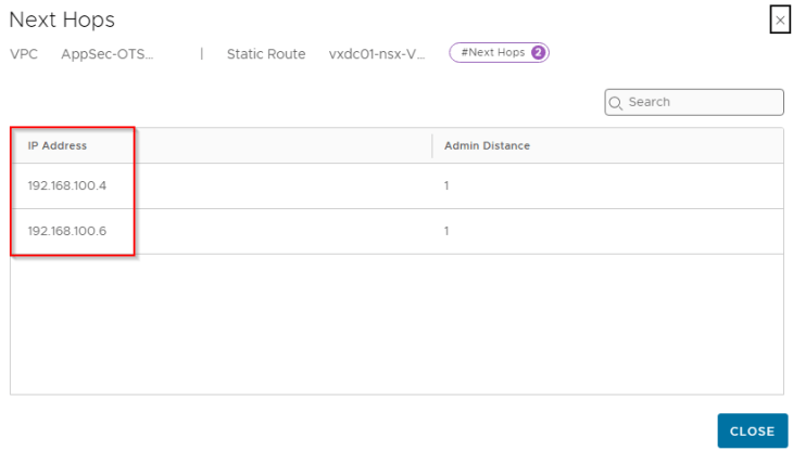
We also see that a static route is auto-configured on the VPC to perform southbound ECMP for the VIPs to the service engines when the virtual services are scaled to two or more SEs.
Excellent!!! You have reached the end of this article.
We covered a lot on NSX multitenancy in our six-part blog series, and I am sure there will be more enhancements in this space coming in the future releases.
This concludes our blog series and we will meet again with a new NSX topic. Stay tuned!!!
I hope the articles were informative, and don’t forget to buy me a coffee if you found this worth reading.

Continue reading? Here are the other parts of this series:
Part 1 : Introduction & Multitenancy models :
https://vxplanet.com/2023/10/24/nsx-multitenancy-part-1-introduction-multitenancy-models/
Part 2 : NSX Projects :
https://vxplanet.com/2023/10/24/nsx-multitenancy-part-2-nsx-projects/
Part 3 : Virtual Private Clouds (VPCs) :
https://vxplanet.com/2023/11/05/nsx-multitenancy-part-3-virtual-private-clouds-vpcs/
Part 4 : Stateful Active-Active Gateways in Projects :
https://vxplanet.com/2023/11/07/nsx-multitenancy-part-4-stateful-active-active-gateways-in-projects/
Part 5 : Edge Cluster Considerations and Failure Domains :
https://vxplanet.com/2024/01/23/nsx-multitenancy-part-5-edge-cluster-considerations-and-failure-domains/


